Test Rig for Small Actuators
Geeplus has developed a new desktop Test Rig designed to provide valuable information on a wide range of electromechanical products with the click of a button.
Geeplus Test Rig for Small Actuators
 Geeplus has developed a new desktop Test Rig designed to provide valuable information on a wide range of electromechanical products with the simple click of a button. This innovative apparatus supplies the user with the most reliable and precise information available, saving both time and money in both production and pre-production environments.
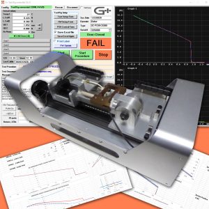
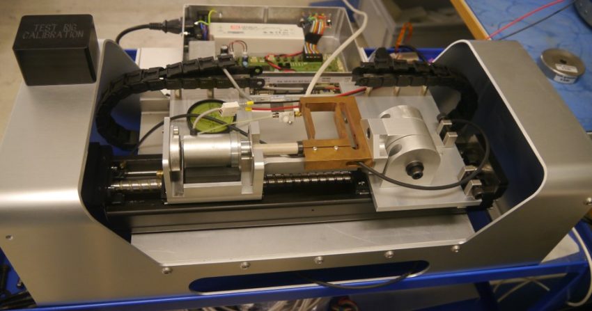
The new test system developed by Geeplus is based around a standard ‘chassis’ incorporating mechanical drive components, load cell, position sensors, and incorporating a purpose designed control unit which provides drive and data logging functions.
The test routine runs on the data logging unit, it can be set up/modified from a connected PC, and the measured data is sent by serial connection to an Excel file in the connected PC.
The time required for each test cycle is determined by complexity of the movement routine, the volume of data transferred to the connected PC, and by the complexity of data manipulation in the spreadsheet (complex graphs and calculations can slow data presentation).
Calculated results set up in the Excel sheet can be populated in several reserved cells, and PASS / FAIL judgment made based on this, the criteria set up in the Excel template in these reserved cells are read back to datalogger and used to make PASS / FAIL judgement of tested parts.
The test rig can be set up to print serialised labels for the test device. The labelled S/N corresponds to test data saved corresponding to the same S/N.
The S/N is automatically incremented if a part passes testing, data is saved, and a S/N label is printed for the device. If a device fails the S/N is not incremented, the user can choose to save data if this is desired to be kept.
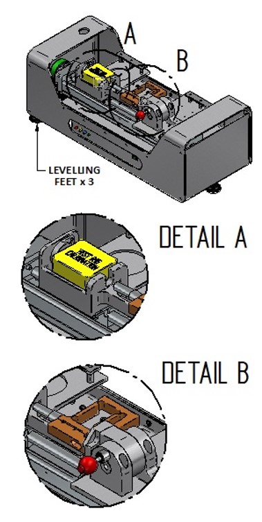
The test rig is shown in the adjacent picture, Detail A shows the sample support area (generic – this varies for different devices), Detail A shows the force transducer and mount.
System Components
A test setup for force vs displacement measurement typically comprises the following components:
Test Rig Chassis
Sample Clamping Fixture (may be part of chassis)
PC with keyboard, mouse, and screen
USB connection cable
Cable and connectors for energizing test sample
Setting pieces and Tools for calibration
The following services are to be supplied by customer:
Power outlet for Test Rig, PC, Monitor
Compressed air supply at 4-8 Bar
![]()
+44(0)208 6567788
Geeplus Europe
Worldwide Customer Service
+1 803 549 6422
Geeplus Inc.
South Carolina (USA)
+81 45 662 9705
Geeplus Asia
Yokohama, Japan
Contact Geeplus
We're here to help - Contact Geeplus today!
Follow us on Social Media
Next Generation Motion Control Solutions!
Geeplus Headquarters:
Triple Two Centre, Tannery Close Beckenham, BR3 4BY, UK
©Geeplus Holdings 2019, All Rights Reserved
Privacy Policy
![]() Offices in Europe | USA | Asia
Offices in Europe | USA | Asia