Technical Library
How to Select a Rotary Solenoid
How to Select a Rotary Solenoid
When deciding on a rotary solenoid for an application, there are a number of factors to take into consideration: Size, torque, and angle of rotation are the basics, but it doesn’t end there. This comprehensive document will walk you through the Geeplus part numbering system for rotary solenoids, helping you to choose the best rotary part, along with any pertinent mechanical and additional options available for your application.
If you have any questions, feel free to contact us any time. You can also fill out our Rotary Solenoid Request for Quote form with any information and specs you have available.
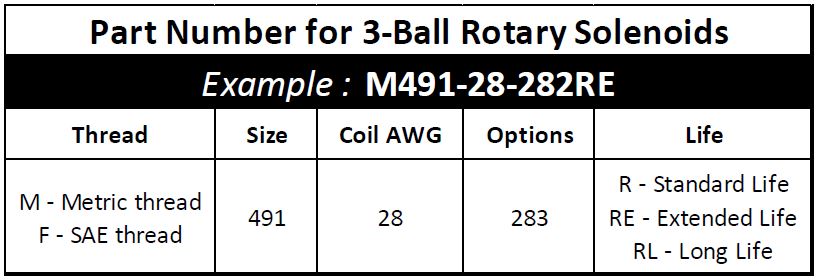
1. Metric (M prefix) and SAE (F prefix) screw thread options are available
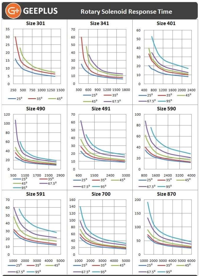
2. The solenoid size is determined from consideration of required torque and effective duty cycle from graphs for the required angle of rotation. This may also be influenced by available power, for a given angle, a larger solenoid will develop the required torque with less electrical power than a smaller device
3. The coil requirements are determined from tables of coil gauge / duty cycle for the chosen size of device. Coil rating is specified as AWG size of the coil wire
4. The mechanical configuration options are chosen to suit the mounting and mechanical attachment of load to the solenoid in the application. These are illustrated later in this selection guide, along with a table which shows how the mechanical options, angle, and direction of rotation are translated into a 3-digit sequence in the solenoid part number. Direction of rotation is defined looking towards the armature plate as shown in attached drawing.
5. The life expectancy of the solenoid is specified by the suffix, R is standard life (2M-5M cycles), RE is extended (5M-10M cycles), RL is long life (20M50M cycles). Life will be reduced by excessive side loading, particulate contamination, corrosive or otherwise aggressive environments. Life expectancy should be verified under real operating conditions in the customer application to ensure this is sufficient for purpose.
Size Determination
Device size is determined for the required torque and duty cycle from the tables below, torque is shown on the vertical axis vs ED on the horizontal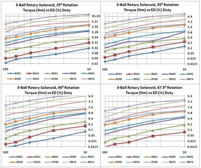
Specifying Coil AWG
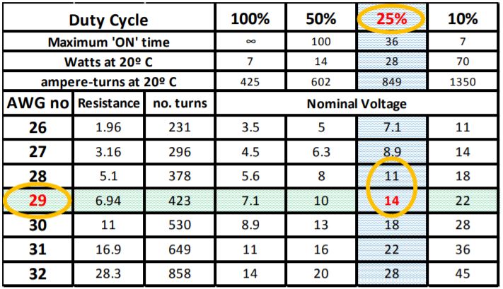
 The coil AWG is determined from tables of coil data for the given part, in the column corresponding to chosen duty cycle, the voltage closest to user supply is picked, and coil AWG corresponding to this is indicated in the LH column (example shows selection for a part operated from 12v supply at 25% duty cycle).
• In the example illustrated, the selection of a device having higher nominal voltage than the supply is conservative, for maximum torque and speed the 28AWG coil might be more appropriate (see also point below)
• Allowance should be made for voltage drops in switching devices, and resistive drops in wiring harness when determining the nominal voltage which will be applied to the solenoid
Mechanical Configuration
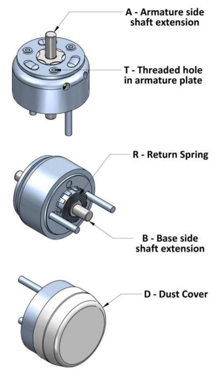
• The direction of rotation of the solenoid is defined looking at the armature plate
• The standard accessories are shown in the adjacent drawing
• The dust-cover option is recomended in any application where the solenoid is exposed to dust which can clog or cause abrasive wear to the inclined raceways. This precludes use of the T option
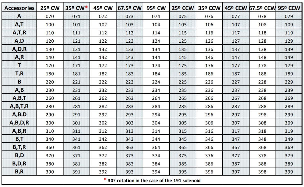
When you have selected mechanical options required, the last 3 numbers of solenoid P/N can be determined from the table below
Thermal Considerations
The coil data for rotary solenoids is based on performance at an ambient temperature of 20⁰C, with the solenoid mounted on a heatsink equivalent to that specified in data. When the solenoid is energised with voltage and duty cycle as specified in the data tables, the coil will reach thermal equilibrium with a coil temperature rise of 85⁰C above ambient temperature. Standard materials will withstand operation at temperatures of up to 120⁰C. If ambient temperature or heatsinking conditions are other than indicated, it is advisable that coil temperature is measured under worst case operating conditions by measurement of coil resistance rise in the energised condition.
Starting Torque
Figures given for starting torque in the solenoid data are gross starting torque with the solenoid energised at 20⁰C. When a return spring is fitted, the net starting torque will be equal to the gross starting torque minus the spring torque.
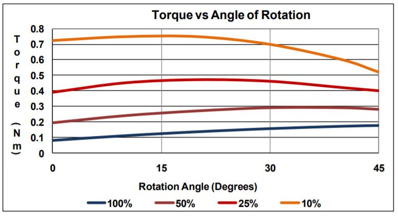
Torque vs Angle Characteristic
The 3-Ball Rotary Solenoid develops rotary torque through mechanical conversion, magnetically the solenoid develops high linear pull-in force along the axis over a short displacement. The rotary torque is produced by 3 helical ball races between the case and armature plate of the solenoid. The inclination of the ball races is not constant, the interaction of this and the magnetic attraction produces a torque which is approximately constant with rotation angle at 25% ED, at 100%ED torque increases as angle increases, at 10%ED torque decreases as rotation angle increases, this is illustrated by the graph below and is typical of all sizes / angles.
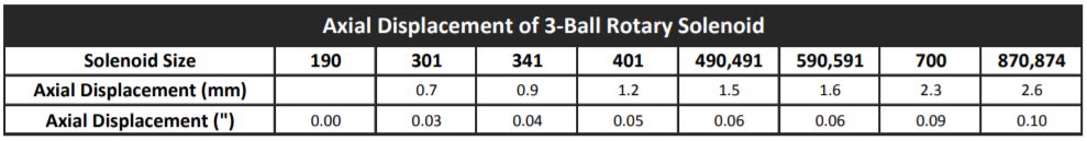
Axial Displacement
A small axial displacement is associated with the rotation of the 3-Ball Rotary Solenoid. The axial displacement developed in different sizes is given in the table below. This is inherent to the design of the 3-Ball rotary solenoid and must be accommodated in the end application.
Restricting the Angle of Rotation
If an application requires an operating angle intermediate to the standard options available, it is possible to limit the rotation angle of the solenoid with an external end-stop, however the following precautions must be observed:
• The external stop should be fitted to limit rotation in the energised direction
• The solenoid must be allowed to return fully to the de-energised position, end stops must not under any circumstances to limit rotation in both directions of rotation
Failure to observe these precautions will result in accelerated failure and invalidates any warranty on the life expectancy of the solenoid.
Use of threaded (A) holes in the Armature Plate
Where the threaded holes in the armature plate are used to attach accessories to the solenoid, caution must be taken that screws are not too long, and do not protrude through the armature plate where they can inhibit linear travel and rotation of the solenoid.
Customisation of the 3-Ball Rotary Solenoid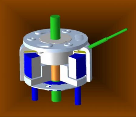
• The drawing indicates which components can be easily modified
o Parts shown in green can be readily modified to customer requirement
o Parts shown in Blue can be modified subject to selection from a range of available components limited by material size (eg length and thread size of mounting studs is constrained by standard sizes available)
• Modified Shaft – shaft modification is a common requirement, and is possible for qty >100pcs
o Longer / shorter shaft
o Flat (D-cut) on shaft
o Cross-hole through shaft
o External screw thread
o Internal screw thread
o Circlip (E-ring) grooves
o Splines / knurling for press-fit to load
• Mounting Studs – longer or shorter mounting studs or other thread forms can be supplied subject to availability of suitable materials for qty >100pcs
• Coil Modification – the following are possible subject to confirmation
o Higher or lower winding resistance
o Double winding for pick & hold operation
o High temperature windings up to 180⁰C
• Return Spring – weaker or stronger return springs are available for qty >100pcs
• Different angle of rotation – this requires significant tooling modification, but may be possible on request for qty >5k-10k pcs
• Leadwires – longer or shorter leadwires can be offered for qty >100pcs
• Modified Armature plate – modification to the armature plate to add crank arms, tabs or other feature is possible for qty >5k-10k pcs
• Drive Pin – addition of drive pins to the armature plate for linkage to the load may be possible for qty >100pcs
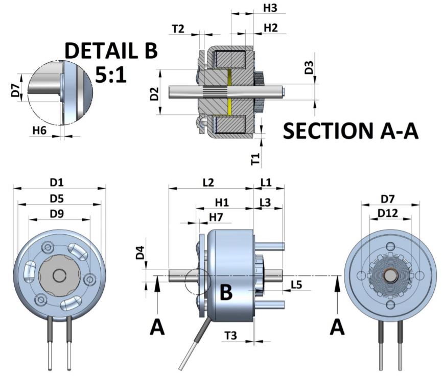
Specifying Modifications
If requesting mechanical modifications to a rotary solenoid, it will be helpful if changes can be specified based on the drawing below. For normal tolerances on different parameters, please refer to tolerances for the standard part on which design is based.
![]()
+44(0)208 6567788
Geeplus Europe
Worldwide Customer Service
+1 803 549 6422
Geeplus Inc.
South Carolina (USA)
+81 45 662 9705
Geeplus Asia
Yokohama, Japan
Contact Geeplus
We're here to help - Contact Geeplus today!
Follow us on Social Media
Next Generation Motion Control Solutions!
Geeplus Headquarters:
Triple Two Centre, Tannery Close Beckenham, BR3 4BY, UK
©Geeplus Holdings 2019, All Rights Reserved
Privacy Policy
![]() Offices in Europe | USA | Asia
Offices in Europe | USA | Asia