Technical Library
How to Select a Linear Solenoid
How to Select a Linear Solenoid / Linear Actuator
There are a number of different factors that can influence the choice of a linear solenoid or actuator; the goal of the selection process is to identify the least expensive device that will satisfy the requirements of the application.
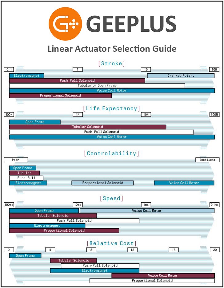
The graphic below is a good place to begin. While factors such as the required stroke and force, along with the duty cycle are 3 key determinants in selecting the right linear solenoid for an application, other elements such as controllability, life expectancy, speed and cost are also taken into consideration.
Force Characteristic & Mechanical Work
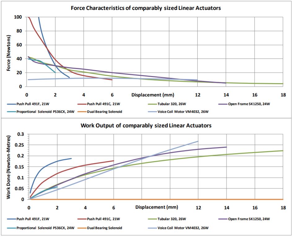
The graphs below show the force vs displacement, and work vs displacement characteristics for different types of linear solenoids with similar weight and power input. It is clear that for short displacement, push-pull solenoids produce much higher force than other types. The flat force characteristic of proportional solenoids and voice-coil motors translates to controllability (control of position), rather than simple ‘on-off’ function. Work carried out by the voice coil is higher because it can drive in both directions; other linear solenoids require a spring to return in the other direction.
Life Expectancy of Different Linear Solenoids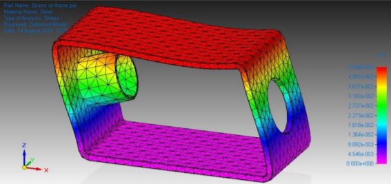 The life expectancy of a linear solenoid is affected by wear of sliding surfaces, and by fatigue and impact failure of component parts. For open-frame solenoids, life expectancy may be limited by fatigue of the steel frame which has limited rigidity. The image shows in exaggerated form how the frame distorts when the plunger impacts the end stop of the open-frame solenoid. under repeated cycles the frame may fatigue and break, typically at the staked joints, or bends in the frame. This mode of failure is more likely to occur with large parts operating at high force and with heavy loads.
 Both the open frame solenoid, and the tubular solenoid, employ a construction in which the plunger slides directly in the sleeve of the solenoid. This may be a brass or stainless steel sleeve, or in some cases the plunger slides directly in the plastic coil former. the plunger and/or sleeve may be treated to reduce friction. Treatments include molybdenum disulphide, nickel plating, Teflon coating and other. These treatments can prolong linear solenoid life considerably to many millions of cycles.
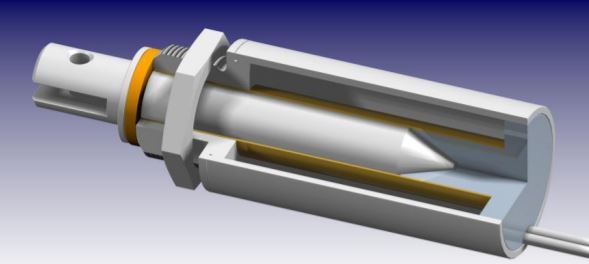
The push-pull solenoid and voice coil motor utilise a separate shaft as bearing surface, as well as bushes of bearing material. These are made from materials well suited to withstand wear, and to manufacture with a fine finish for optimum wear life.
Follow us on Social Media
Next Generation Motion Control Solutions!
Geeplus Headquarters:
Triple Two Centre, Tannery Close Beckenham, BR3 4BY, UK
©Geeplus Holdings 2019, All Rights Reserved
Privacy Policy
![]() Offices in Europe | USA | Asia
Offices in Europe | USA | Asia