Technical Library
Proportional Solenoid Actuators:
General Technical Information
Proportional Solenoid Actuators: General Technical Information
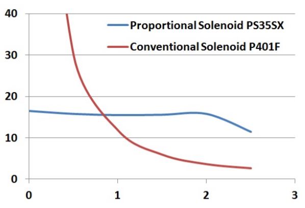
Most solenoids are simple 2‐position ‘digital’ devices, the proportional solenoid actuator however is an analogue device capable of incremental positioning. The design of the polepiece of the proportional solenoid results in a force being developed which is constant over some displacement (the ‘control stroke’), and which is proportional to the excitation current.
Proportional solenoids can be used to develop a force which is directly proportional to current, or with the addition of a rising‐rate spring to extend to a position which is proportional to current.
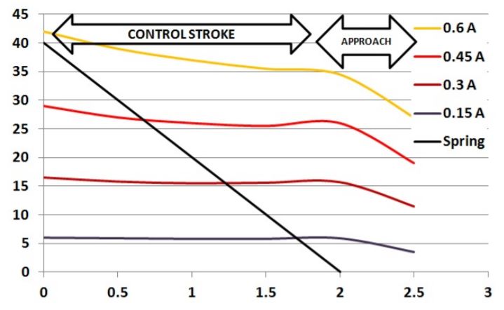 As the excitation current increases, the force developed by the solenoid increases. The solenoid plunger pulls in until the magnetic force is balanced by the opposing spring force. As the current is increased, it will pull in further to attain a new equilibrium position. In this way, a system is realised in which the position is proportional to the applied excitation current. As a simple analogy, increasing the current is like adding additional mass to a spring balance, as the mass increases, the spring is extended further until an equilibrium is reached.
 Hysteresis
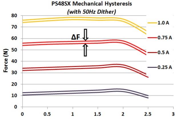
The force characteristic for a proportional solenoid actuator is typically shown as a pair of lines to take account of a property known as hysteresis. If the solenoid is tested by pushing the plunger against the direction in which force is developed, the measured force includes some friction which opposes the movement and adds to the developed force, if the plunger is then allowed to return in the direction of force the friction retards this movement and results in the measured force being less than the developed force, the difference between these two curves is a measure of (mostly*) mechanical hysteresis.
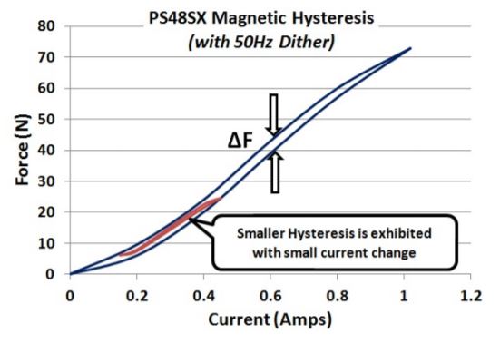 If the force developed by the solenoid is measured in a fixed position as the current is increased, another curve can be plotted which is a loop as shown, the force difference between upper and lower curves in this case represents (mostly *) magnetic hysteresis caused by losses in the magnetic steel material.
Hysteresis losses will limit the precision to which force or position can be accomplished using a proportional solenoid actuator. Mechanical hysteresis will vary for different bearing types, for dry / maintenance free bearings it will typically be 10‐20% of the developed force, for lubricated bearings, or for flexure supports it can be smaller.
Note * ‐ some care should be taken in describing these parameters as ‘mechanical’ or as ‘magnetic’ as measurement of either will include some element of the other parameter.
The effect of Hysteresis on control of the solenoid is described with reference to the graph below.
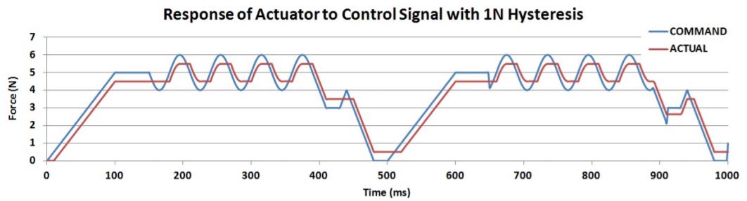
The ‘COMMAND’ line represents the force developed by a perfect solenoid, without friction or magnetic hysteresis. The ‘ACTUAL’ line represents the force that would be measured in practise at the output shaft of the device.
Dither
Dither is an electronic signal superimposed on the signal driving a proportional (or other) solenoid, which can mitigate some of the effects of hysteresis. An AC signal (the ‘Dither’ signal) is superimposed on the ‘COMMAND’ signal applied to the solenoid. The effect is shown in the graph below.
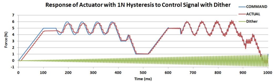
As the amplitude of the dither signal increases, the deviation of the ‘ACTUAL’ force from commanded value will reduce, reaching a minimum when the peak‐to‐peak amplitude of the dither signal corresponds to the solenoid hysteresis. If dither amplitude is increased further, the solenoid will begin to exhibit some oscillation about the commanded value.
Dither can be a very effective way to mitigate the effects of hysteresis, provided the amplitude and frequency can be matched to characteristics of the solenoid used.
The way in which dither works may be better illustrated with reference to the graph below.
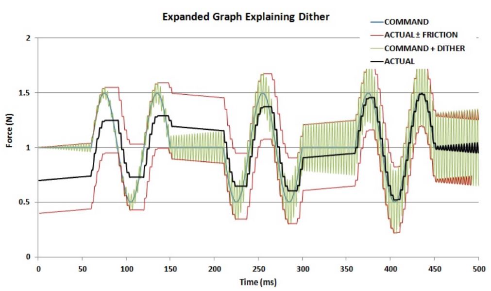
The two red lines represent the actual output force of the solenoid plus or minus friction (half of the hysteresis value). Without dither the actual force will lag the ‘commanded’ force by this amount. As dither is added to the command signal. It causes the upper and lower values of the resultant signal to vary, as the signal increases, the ‘high’ value of the signal nudges the output force upwards, as the signal decreases the low value does this, with the result that the actual force or position more closely follows the commanded value.
When the amplitude of the dither signal corresponds to the hysteresis value, the actual output will accurately follow the commanded value. If dither is increased more than this, the average value of the actual force will follow the commanded value, but will have an oscillating component corresponding to the frequency of dither.
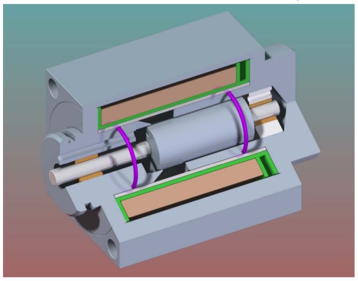 Hydraulic Solenoid
Solenoids can be constructed with a sealed cavity connecting the mounting face of the solenoid to the base pole piece. The image shows a proportional solenoid which is constructed in this way. In this case the device is shown as having o‐ring seals sealing the front and rear pole pieces into a metal tube, alternatively these may also be assembled using a welded, brazed, or glued construction to seal and fix the parts of the pressure assembly. Hydraulic solenoids can be constructed capable of operating at pressure of 20MPa / 3000PSI or more. The plunger and pole pieces typically incorporate channels to allow the free passage of fluid throughout the device. Because the fluid is able to flow around all moving parts of the assembly at equal pressure, the fluid pressure does not affect the force characteristics of the solenoid.
Hydraulic solenoids can be produced with either proportional, or with simple 2‐position ‘ON‐OFF’ function.
![]()
+44(0)208 6567788
Geeplus Europe
Worldwide Customer Service
+1 803 549 6422
Geeplus Inc.
South Carolina (USA)
+81 45 662 9705
Geeplus Asia
Yokohama, Japan
Contact Geeplus
We're here to help - Contact Geeplus today!
Follow us on Social Media
Next Generation Motion Control Solutions!
Geeplus Headquarters:
Triple Two Centre, Tannery Close Beckenham, BR3 4BY, UK
©Geeplus Holdings 2019, All Rights Reserved
Privacy Policy
![]() Offices in Europe | USA | Asia
Offices in Europe | USA | Asia