Technical Library
Leadscrew Actuators:
General Technical Overview
Leadscrew Actuators
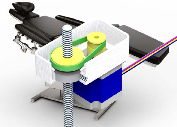
Leadscrew Actuators produce linear movement from the rotation of a rotary motor. They are used in a variety of applications, including position adjustment of hospital beds and furniture, machine tool actuation, valve actuation, and others.
 Leadscrew Options
The screw thread design, along with the materials and finish of the leadscrew and nut, can have a sizable impact on efficiency. A trapezoidal thread profile and rolled thread construction are desirable for strength and efficiency. Low friction polymer material, or lubricated metal are desirable for the nut.
A small leadscrew diameter will reduce friction losses, but may result in higher pressure and faster wear between the leadscrew and nut.
The rotating element of the actuator needs to be supported by a bearing having sufficient load capacity to support the axial load.
Different types of motors can be used. Stepper motors allow low-cost open-loop control, while brushless DC motors produce less audible noise, and have higher rotational speed capability.
Where high forces are required, a small lead – or use of a timing belt reduction mechanism – are preferred to achieve the maximum mechanical advantage.
 Theory of Operation
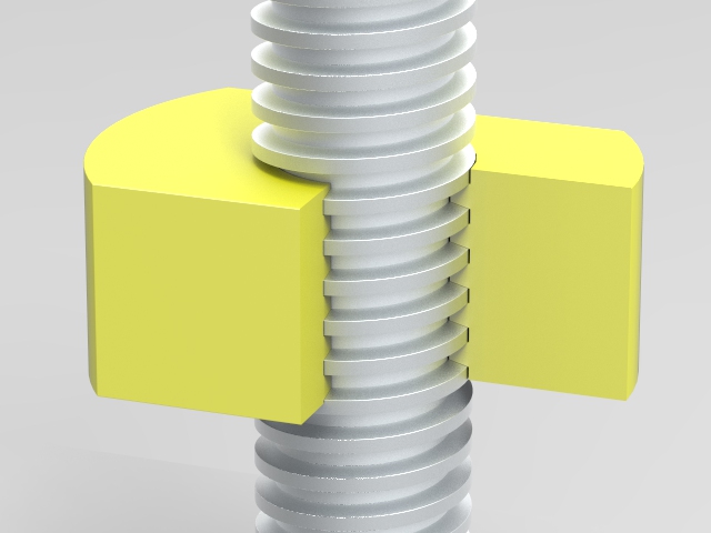
Leadscrew actuators are based on a threaded rod and matching nut. One of these two elements is turned by a motor, either mounted directly to the motor shaft, or coupled by gears, belt, or other mechanism. The other element is attached to the component to be moved, and constrained so it cannot rotate. The relative rotation of the two elements causes a linear movement along the axis.
There are two components to the torque required to turn the rotating element of a leadscrew:
Friction torque – the load (F) applied along the axis is assumed to be applied to the outside diameter (D) of the leadscrew, acting at a radius of D/2. Where the friction co-efficient between the two elements is μ, a friction torque component (T1) is calculated as follows:
T1 = μ x F x D/2
Actuation torque – the actuation torque component (T2) is calculated by equating mechanical work (assuming 100% efficiency) for 1 revolution.
The mechanical work carried out in one revolution is calculated by multiplying the load force (F) by the lead (L) of the screw elements (the displacement produced for 1 revolution).
The rotary work is obtained by multiplying the actuation torque (T2) by the angle in radians (2 x π) translated in one revolution.
T2 = (F x L)/(2 x π)
So the total torque required to turn a leadscrew is given by:
T = 0.5 x F x ((μ x D)+(L/π))
This equation simplifies the losses due to friction. Efficiency may be worse than assumed in this.
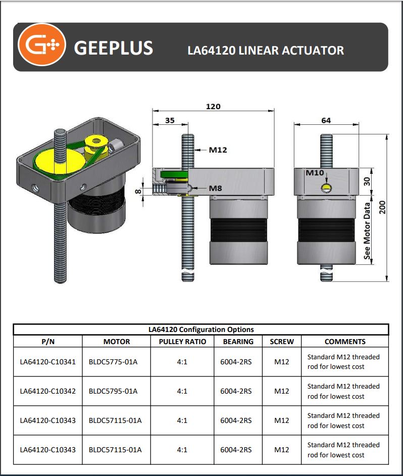
Leadscrew Actuator Technical Data Sheet
![]()
+44(0)208 6567788
Geeplus Europe
Worldwide Customer Service
+1 803 549 6422
Geeplus Inc.
South Carolina (USA)
+81 45 662 9705
Geeplus Asia
Yokohama, Japan
Contact Geeplus
We're here to help - Contact Geeplus today!
Follow us on Social Media
Next Generation Motion Control Solutions!
Geeplus Headquarters:
Triple Two Centre, Tannery Close Beckenham, BR3 4BY, UK
©Geeplus Holdings 2019, All Rights Reserved
Privacy Policy
![]() Offices in Europe | USA | Asia
Offices in Europe | USA | Asia