Technical Library
How to Use the Pick and Hold Module
How to Use the Pick and Hold Module (PHu-50)
REQUIREMENTS
A PHu-50 module is required, with USB-Micro cable, and PC with programming Software PHprogrammer.exe V6.0+. Other than these items a load device is required, and Power Supply able to supply voltage and current appropriate to the application, and within the limitations of the PHu module being used.
SOFTWARE INSTALLATION
The folder containing software should be copied to the PC being used for programming. It is recommended that the complete folder is copied as it is important that all the programmes are in the same folder on your PC.
The Setup program “CDM212364_Setup.exe” should be run to install the USB drivers required to use the PHu-50 module. The latest driver is downloadable from https://ftdichip.com/drivers/
Double clicking the ‘PHprogrammer’ icon will start the programming software.
PHu CONNECTION
The PHu-50 module has 7 connections on a WAGO terminal block, to connect to these simply push down the white button on top of the terminal block as stripped lead is inserted in the corresponding hole.
 The positive supply (+Vpwr) is connected to terminal 4, and ground to terminal 5, and should be in the range of 8-50V. DO NOT apply voltage greater than 50V DC as this will damage the module.
Reverse voltage causes high current flow though the reverse diodes. They protects the module for short time, but if overheating then this may damage the module.
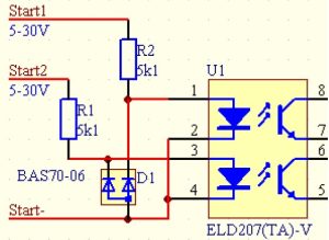
Terminals 1 (Negative), 2 (Start1) and 3 (Start2) are the opto-isolated control inputs. The input circuit is as shown below, applying 5v-30v to this will switch the circuit ‘ON’. Higher control voltage may be used if appropriate serial resistor is inserted to limit the input current to 6mA.
The PHu-50 module have 4 operating modes. Each of them requires the corresponding wiring of the load(s) . The programmer software appears differently for each mode, showing it below together with the wiring diagrams.
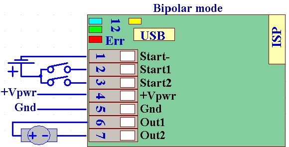 1. Bipolar mode (default): The module drives one bipolar solenoid, connected between terminals 6-7 (Out1-2). The Start1/2 inputs controls the solenoid to positive/negative directions, respectively. LED1(Blue) indicates Active-Positive, LED2(Green) indicates Active-Negative
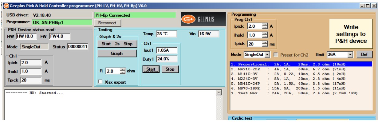
2. SingleOut mode: This is similar to the Bipolar mode in positive direction. LED1(Blue) indicates Output Active
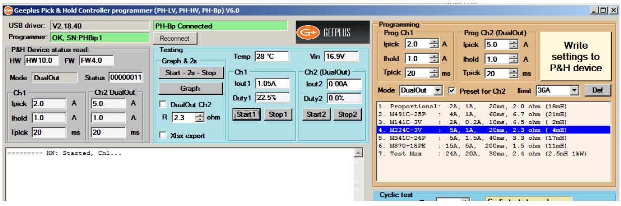
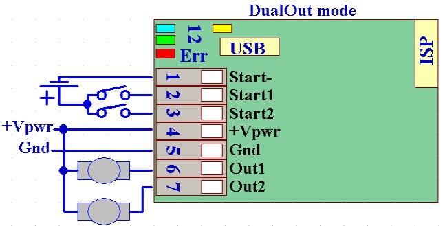 3. DualOut mode: The module can drive two solenoids in this mode. They should be connected between +Vpwr and Out1, +Vpwr and Out2. The Start1/2 inputs controls the solenoids. LED1(Blue) indicates Out1-Active, LED2(Green) indicates Out2-Active. Both channels have their individual current and time settings.
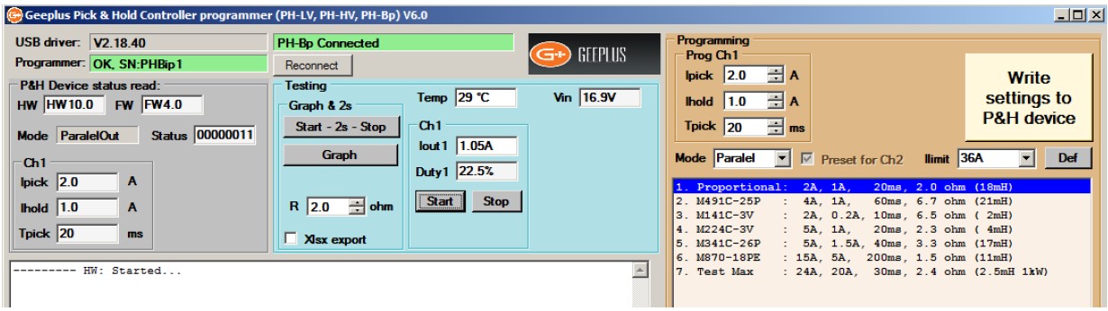
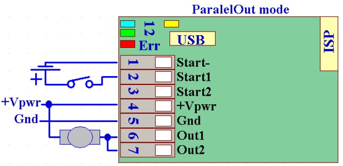 4. ParalelOut mode If only one solenoid will be driven, the two outputs (Out1/2) can be connected in paralel. This operation reduces the power lost on the output stages, allowing higher continuous current, and less temperature rise. The load should be connected between +Vpwr and Out1-Out2 as shown. The Start1 input controls the solenoid. LED1(Blue) indicates Out1-2 Active.
For setup & testing while the module is connected to a PC it is possible to switch the solenoid on (‘START’) and off (‘STOP’) from the PC without using the control input.
In addition to ‘START’ and ‘STOP’ control buttons, the software also has a timed BUTTON ‘START – 2s – STOP’ which energises the test device for 2 seconds only. This function is recommended for initial testing of force as the timed pulse limits the amount of energy delivered, and so limits the self-heating and reduces the possibility of overheating and damaging the solenoid’. Once it has been established that sufficient force can be developed, the thermal behaviour of the system should be considered to ensure the chosen device will not overheat.
PROGRAMMING
The Phprogrammer V6.0+ supports all kinds of the Phu modules:
-PHu24, Phu-HighVoltage (requires special USB programmer cable)
-Phu-50-Bipolar (built-in USB port, Standard USB-Micro cable is usable)
The connected module identified automatically.
Here the Phu-50 module will be described. The software operates with the others like Phu-50 in SingleOut mode.
The USB cable plugs into the USB-Micro socket above the WAGO terminal block. If a Phu-50 Bipolar module is connected for the first time to this PC, Windows will install the USB driver for it in the background, this may take 10s.
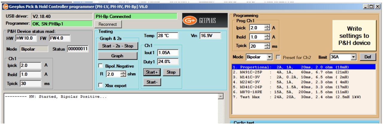
With a load and power supply connected and turned on, the programming software is run. The programme should recognise if a PHu module is connected and powered, if this is not recognised click on the button labelled ‘Reconnect’ to reconnect. You should see the screen as below:
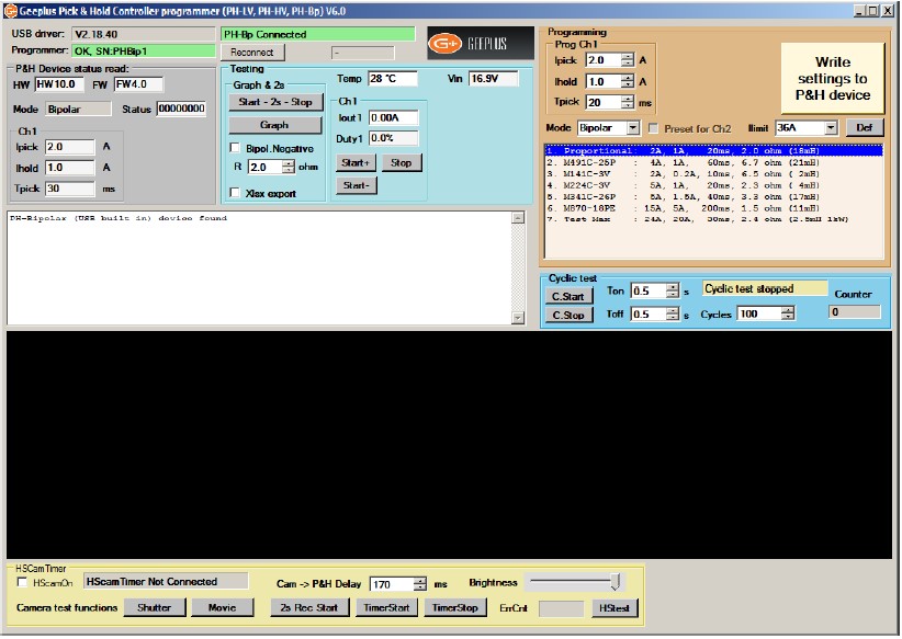
Note the programmer reads the actual settings from the module, and it will appear with different controls regarding the actual Mode (above showing Bipolar).
As it opens up, the programmer defaults to the smallest values for safety, you can pick a device of appropriate size as a starting point, press the button ‘Write Settings to P&H Device’ to store these settings in the module.
You can edit the ‘Pick’ and ‘Hold’ current settings and ‘Pick Time’ as desired before writing settings to the module.
For setting up current values, you can use the grey buttons to switch the load device ‘On’ and ‘Off’ without using the control input connections.
MONITORING
While the solenoid is energised (‘ON’ condition), the programme interface monitors the operating conditions.
Temp – this is the internal junction temperature of the switching device, this should not exceed 120 degC when the module is being used in worst-case conditions. If the junction gets much hotter than this internal protection will shut the device down
Vin – The +Vpwr input voltage (Only on Phu-50 Bipolar modules)
IOut – the output current
Duty – The duty cycle of PWM waveform
After de-energising the solenoid (‘STOP’ condition), the operating current and duty cycle for both pick and hold conditions of the last ‘ON’ cycle are summarised in the white text box.
If the programmed current is too high, then the current will not be able to reach this value as it will be limited by supply voltage and / or coil resistance of the load. Either a lower resistance device, or higher supply voltage may be required. It should be noted that although a device may work OK in the cold condition, as it heats up the coil resistance will rise. In the cold condition, the duty cycle should typically be 70% or less to allow for this.
STATUS INDICATORS
Three LED’s provide status indication.
The BLUE and GREEN LEDs indicates The Active status, detailed above for all modes.
The RED LED indicates an ‘ERROR’ conditions: Overcurrent or Overtemperature.
SELECTION OF SOLENOID FOR PICK & HOLD
This is a general guide as requirements of an application may dictate other constraints on Pick and Hold current levels.
 As a very rough guide, a solenoid should be selected which is operating at about 5-10% duty cycle at the system voltage. If the solenoid coil is specified by voltage (at 100% ED), then the coil voltage chosen should correspond to Vsupply / √10, if the solenoid coil parameters are presented in a table then pick a coil which provides operation at 10% ED at the rated supply voltage.
Ideally, the solenoid should be mounted in the end application, and set up with worst-case operating conditions (maximum ambient temperature, minimum supply voltage).
With the circuit connected to a PC, the ‘Pick’ and ‘Hold’ currents and ‘Pick Time’ duration can be adjusted to determine conditions which satisfy the force, speed, and power requirements of the application.
For applications where high force is required to overcome a large load, the pick time may need to be sufficiently long for the solenoid to pull in to the energised position and settle before current is reduced to the holding level.
For applications requiring high speed, it may be preferable to drive with maximum possible power for a very short ‘pick’ time, as the initial acceleration has greatest influence on the overall response time.
When the device is switched off, the text box in programming software will display the current and duty cycle for both pick and hold operation. Ideally the duty cycle should be within the range of 10-90%, the module can operate outside this range but this leaves some leeway for variation in supply or temperature conditions.
The junction temperature of the power MOSFETs is displayed, this should not exceed 120°C max under worst case conditions.
![]()
+44(0)208 6567788
Geeplus Europe
Worldwide Customer Service
+1 803 549 6422
Geeplus Inc.
South Carolina (USA)
+81 45 662 9705
Geeplus Asia
Yokohama, Japan
Contact Geeplus
We're here to help - Contact Geeplus today!
Follow us on Social Media
Next Generation Motion Control Solutions!
Geeplus Headquarters:
Triple Two Centre, Tannery Close Beckenham, BR3 4BY, UK
©Geeplus Holdings 2019, All Rights Reserved
Privacy Policy
![]() Offices in Europe | USA | Asia
Offices in Europe | USA | Asia