Technical Library
Control Circuits: Pick and Hold Module
General Technical Information
Control Circuits: Pick and Hold Module General Information
Control Circuit Description
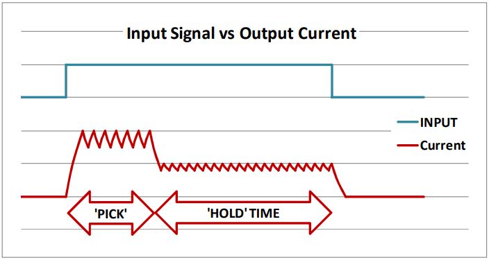
A Pick & Hold circuit regulates current applied to a solenoid or motor, applying high initial current (PICK) to develop high initial force/torque for fast response, then reducing this after a preset time (PICK TIME) to a lower level (HOLD) to maintain operation.
It can be used to reduce power consumption in applications with restricted power supply (eg battery or line-powered systems), to reduce heat and power dissipation (systems handling temperature-sensitive materials, or susceptible to thermal distortion), or to stabilise performance of systems against fluctuations in supply voltage or ambient temperature.
 Geeplus PHu modules are microprocessor controlled pick & hold modules which use intelligent algorithms to control a wide range of devices with simple user control of current and time parameters.
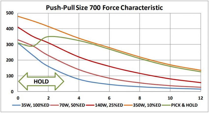
The graph below shows the characteristic force curves for a push-pull solenoid (the curves at different excitation power showing greater force with increasing excitation power, and the shape of the curve with force increasing as displacement reduces towards zero are similar for most linear solenoids), the use of a pick and hold circuit enables force to be realised at the extended position similar to an intermittent duty curve, with continuing excitation power comparable to (or even lower than) that of the 100% duty curve.
The PHu modules can be used to implement control of large solenoids in an end-user application, the user-friendly interface also makes them a superb development tool to explore the maximum performance achievable from a wide range of solenoids during product development.
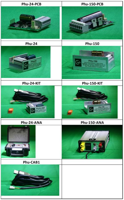
Product Table Available versions are detailed below.
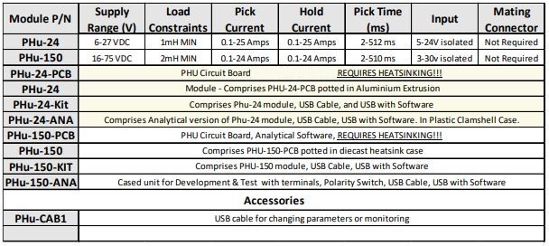
Please note that the continuous excitation (Hold) current may be limited by heat dissipation.
Warning – if maximum Supply Voltage is exceeded by more than 10% permanent damage may be caused to the module
Setup
Both modules should be setup before use, using the Pick and hold software and USB cable which is included in the kit versions. A user friendly interface allows current and time parameters to be set up and saved, and also allows monitoring of the switching device temperature to confirm operation is within safe limits in a wide range of ambient conditions.
Further information on our website – https://www.geeplus.com/how-to-use-the-pick-and-hold-module/
PHu Product Configurations
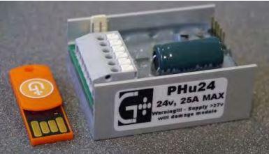
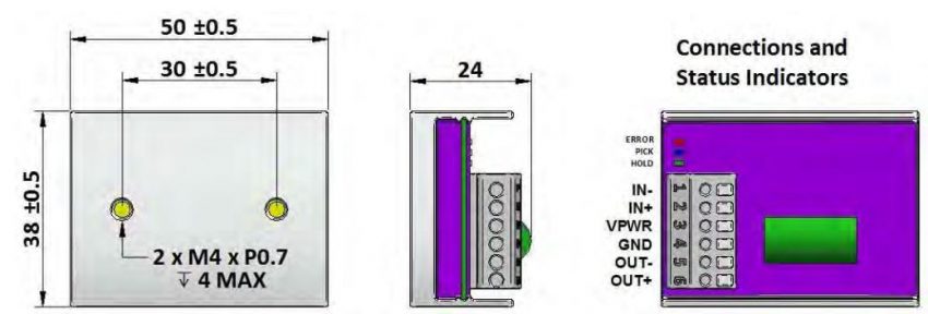
PHu24 – Mechanical Dimensions
Standard module configuration is mounted in extrusion and potted (encapsulated) with epoxy resin.
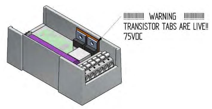
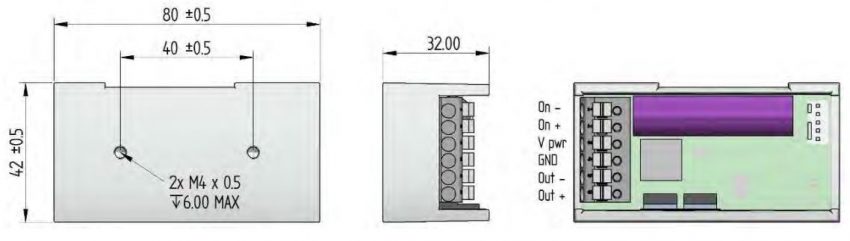
PHu150 – Mechanical Dimensions
Standard module configuration is mounted in extrusion and potted (encapsulated) with Clear epoxy resin.
![]()
+44(0)208 6567788
Geeplus Europe
Worldwide Customer Service
+1 803 549 6422
Geeplus Inc.
South Carolina (USA)
+81 45 662 9705
Geeplus Asia
Yokohama, Japan
Contact Geeplus
We're here to help - Contact Geeplus today!
Follow us on Social Media
Next Generation Motion Control Solutions!
Geeplus Headquarters:
Triple Two Centre, Tannery Close Beckenham, BR3 4BY, UK
©Geeplus Holdings 2019, All Rights Reserved
Privacy Policy
![]() Offices in Europe | USA | Asia
Offices in Europe | USA | Asia