Technical Library
What is a Latching Solenoid?
General Technical Information
What is a Latching Solenoid? General Technical Paper
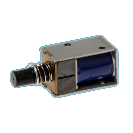
Latching solenoids come equipped with a permanent magnet, exhibiting magnetic attraction between the plunger and pole piece with no electrical power applied.
Properties of the Latching Solenoid
 With a spring or other load providing return force, the latching solenoid requires only a momentary excitation pulse to change position conferring the following advantages on these devices:
• Power consumption is zero to hold in either end position – this is advantageous for systems with limited power supply such as battery powered devices, or devices powered by telephone line power, or solar power.
• Power dissipation (heat) is zero in the holding condition – this is advantageous to handling temperature-sensitive materials such as photochemicals, blood products, or chemical reagents.
• There is no radiated electrical noise in the holding condition (there is a fixed magnetic field due to permanent magnets), this can be advantageous in sensitive measuring circuits.
• The ability to hold end position without power, can allow higher power to be applied during the excitation pulse for a given size of device without causing heating problems, this can allow higher operating speed to be realised, or allow a smaller device to be used to move the load in a given application.
 The latching solenoid is ideally suited to applications where the ‘moving’ time is very short compared to holding time in the end position, and where the system may be required to maintain either end position for a prolonged period.
It should be recognised that latching solenoids are unsuited to applications requiring ‘failsafe’ operation (where the system should move to a known state in the event of power failure) unless complex drive circuits with energy storage are employed. Where fail-safe operation is required alternative solutions (such as pick & hold circuit) should be considered.
 Construction of the Latching Solenoid
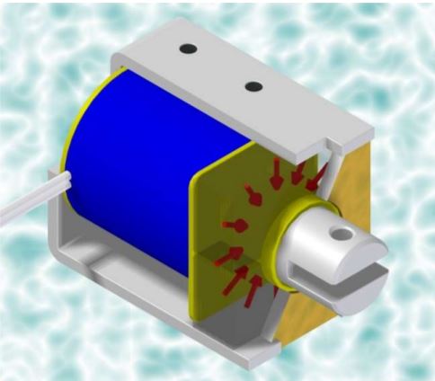
The Latching Solenoid incorporates permanent magnets within it’s construction, in such a manner that these drive flux around the magnetic circuit when the device is in a deenergised condition developing force without any externally applied excitation. The most common configuration based on an open-frame construction is illustrated, with cutaway sections, and with the magnet blocks drawn as transparent material to clarify the construction. The red arrows represent flux developed by the permanent magnets.
Forward excitation of the Latching Solenoid
In the de-energised condition the permanent magnets drive magnetic flux around the solenoid, this is sufficient to develop useful holding force when the airgap between plunger and pole piece is very small, but only to develop a small pull-in force from an extended position. This is represented by the black line in the characteristic graph. These curves are interpreted with reference to the Force and Displacement axes of the graph.
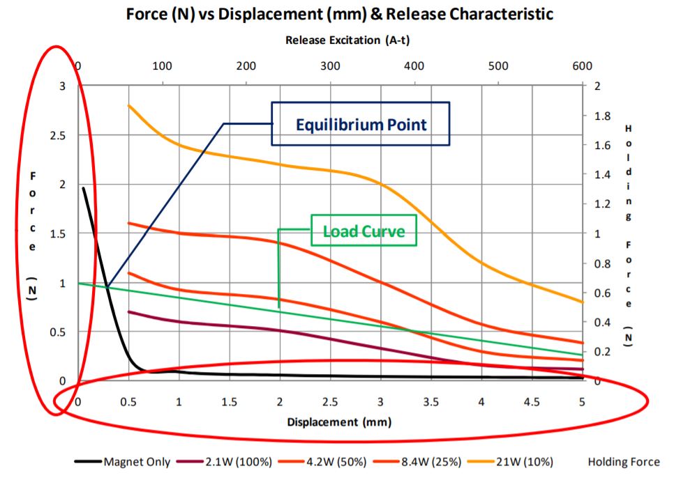
When the latching solenoid is energised with current in the forward direction, the excitation of the coil induces magnetic flux reinforcing the field due to the permanent magnets. As the excitation current increases, the force developed increases.
Bistable Operation
The characteristic graph also shows a load line as would typically be produced by a spring, it should be noted that this would normally be acting in the opposite direction from the magnetic attraction force. It is evident that at short displacement – to the left of the equilibrium point – the magnetic attraction force due to the magnets alone is stronger than this load force, in this region the plunger will be held in the solenoid with no external power being applied. To the right of the equilibrium point, the outward force developed by the spring is greater than the magnetic attraction force, the plunger will move out to the extended position. In the de-energised state this solenoid / load system is bistable and will hold either end position without external power. The solenoid can be driven from the extended to the retracted position by the application of a forward current sufficient to develop magnetic attraction greater than the load force, in this case >8.4W.
Release Operation of the Latching Solenoid
When excitation current is applied to a latching solenoid in the reverse direction, it opposes and neutralises the field developed by the magnets. As current is increased, the flux flowing due to the permanent magnets decreases until at some point flux ceases to flow around the magnetic circuit and attraction force between plunger and pole piece falls to zero, as current is increased further flux begins to flow around the magnetic circuit in the reverse direction and attraction force is again developed between the plunger and pole piece.
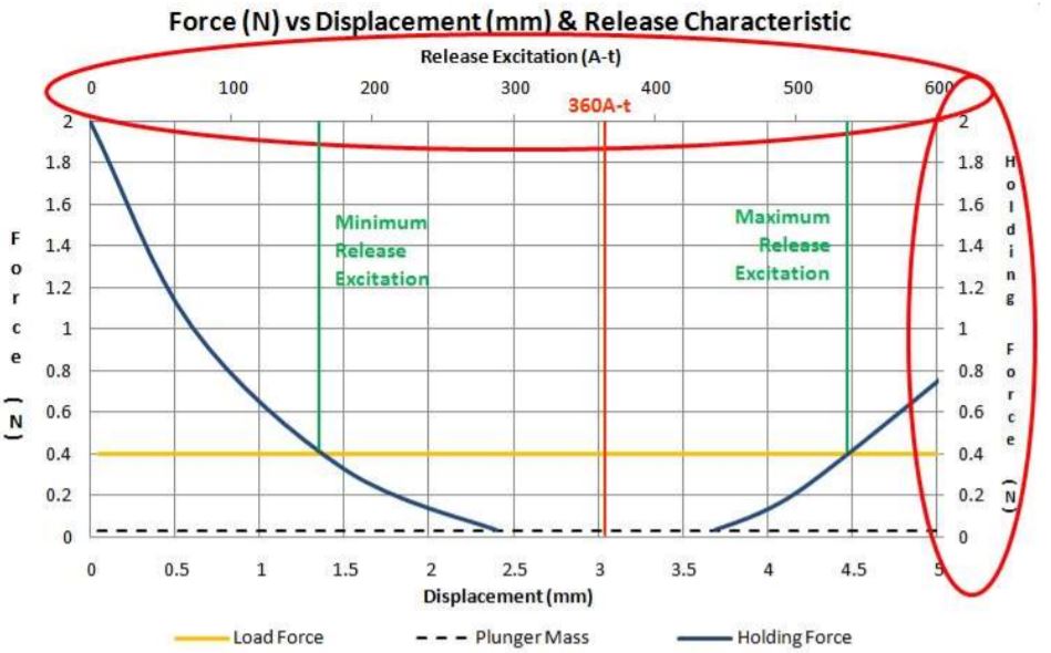
The Holding force characteristic is interpreted with reference to the Holding Force and Release Excitation axes on a characteristic graph. If the load force acting on the solenoid plunger is known, a line corresponding to this can be plotted on the characteristic.
The solenoid will release the load when reverse excitation is in the region between the two green lines drawn from intersection between the load and holding force curves. The release characteristic is normally plotted to intersection with a line corresponding to the plunger mass. A release current may be specified in data for the solenoid which is in the middle of the range in which the plunger will drop out with the solenoid mounted vertically and with no additional load.
It should be noted that with a higher load force, the range of excitation current at which the solenoid will release will be wider.
The graphical data for release characteristic shows excitation in Ampere-turns (this is independent of temperature or winding option), this value should be divided by the number of coil turns to determine the release current required for a specific winding option.
Determining Release Current for Latching Solenoid
There are several additional factors which should be considered when determining the appropriate release current for a latching solenoid.
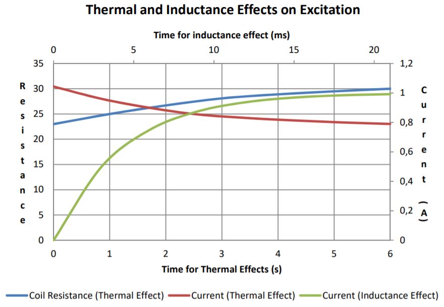
• The solenoid is an inductive load. When connected to a voltage source, the current will rise exponentially towards a stable value, due to this characteristic it will not instantaneously reach the ‘target’ level. To ensure current rises quickly to the level needed for release, it may be desirable to aim for a target level for the release current which is near the top of the release range.
• If the coil is energised for a prolonged period, it will heat up due to ohmic dissipation, as it does so the coil resistance will increase. If the solenoid is energised from a voltage source, the current will decrease in inverse proportion to the increase in resistance. In this case, or if ambient temperature is exceptionally high or low, then the target excitation should be revised accordingly.
If excitation is from a current source, susceptibility to temperature variation will be eliminated, susceptibility to variation in source voltage will also be lessened.
 If the application is subject to higher or lower ambient temperature conditions, then the target release current may need to be modified accordingly.
 Electrical Drive
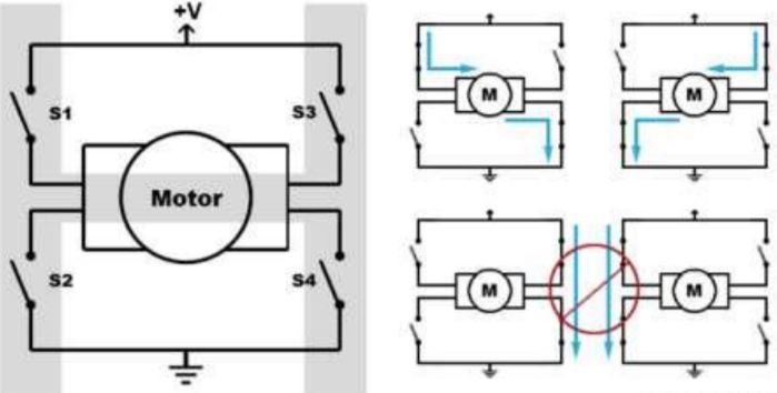
To drive a bistable rotary solenoid, a circuit configuration known as an H-Bridge is normally required. This is shown schematically. This is normally implemented using solid state switches (transistors), a number of integrated devices are available to simplify implementation of such a circuit.
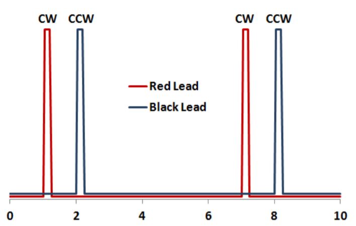
By closing either S1 and S4, or S2 and S3 while the other switches are open, the current can be caused to flow through the solenoid coil in either the forward or the reverse direction. With momentary excitation pulses as depicted in the timing diagram the solenoid can be pulled in or released, remaining in either position with no power applied in between.
![]()
+44(0)208 6567788
Geeplus Europe
Worldwide Customer Service
+1 803 549 6422
Geeplus Inc.
South Carolina (USA)
+81 45 662 9705
Geeplus Asia
Yokohama, Japan
Contact Geeplus
We're here to help - Contact Geeplus today!
Follow us on Social Media
Next Generation Motion Control Solutions!
Geeplus Headquarters:
Triple Two Centre, Tannery Close Beckenham, BR3 4BY, UK
©Geeplus Holdings 2019, All Rights Reserved
Privacy Policy
![]() Offices in Europe | USA | Asia
Offices in Europe | USA | Asia